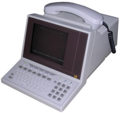
Siemens Multitel Fe Ap 90-1.1
Another unit based on Siemens Bitel T3210 design. After some success of "intelligent telephone", Siemens manufactured other types of this terminal, here is a newer version of T3210. This one is known as "Multitel Fe Ap 90-1.1". It was not marked with Siemens logo, but with German Post office logo and stickers so it was probably leased from Post for operation as Bildschirmtext service terminal. It is newer than T3210 - my unit is from 1988 (?89) while Bitel is 2 years older. The construction has been simplified - re-designed mainboard contained only one ROM containing data essential for operating - mostly characters and graphics - and the system ROM has been moved to battery-backed SRAM module. This way it could be upgraded without much disassembly. Lock module ROM is not used at all. DB expansion connector has been replaced with two DIN ones and card reader conector is not soldered in. It was definitely a "cost-reduced" and upgraded version of T3210. Its strange name - "Fe Ap" may come from German "Fernsprech Apparat" - Telephone device, as well as e.g. "Fernschreiber" - a teletype especially that some German telephones had types "FeT Ap ...".
| Manufacturer: | Siemens | |
| Model | Fe Ap 90-1.1 | |
| Year: | 1986 | |
| CPU: | Intel 8742 | |
| Memory: | 4+2kB onBoard 32kB in battery-backed expansion |
|
| Display: | CRT, monochrome, white | |
| Keyboard: | Built-in | |
| Main port: | Telephone line | |
| Additional ports: | 3 unknown DIN connectors, one probably for
serial printer. Telephone line for primary connection with network (German-type plug)
|
|
|
Peripherals in collection: |
My unit is in good condition and has a key in lock. It powers on and can be operated in limited (by lack of BTX service) range.
Disassembly:
First, check for one screw in the bottom, right behind
keyboard. It may be present or not.
Then, use screwdriver to unlock front panel by putting it in two holes
on the upper side of the computer. Pull the front panel towards you, it
should open leaving CRT and keyboard.
You can remove keyboard by sliding it and pulling, don't break ribbon
cable.
To remove cover, take it with two hands in bottom near front and pull
away from the computer and upwards - it will unlock and open to the
rear.
It's time to remove boards. Disconnect topmost speaker, then unlock
spring rod and slide the boards off the chassis.
Removing CRT/power supply compartment is more difficult, You need to
unlock two plastic bolts on the very rear on sides, then pull a whole
CRT compartment towards keyboard and make it open on the front part.
When it'll be in quite large angle it will be possible to remove it.
Mainboard should be visible then.
If you want to remove display board only, you may need to remove high-voltage cable from CRT too. Or it will pop out by itself.
Opening the lock without key
Starting, key operation
Let's start with a key. Look from the above of the
terminal.
"-" - When the key is in horizontal position, it allows all operations
of the device.
"\" - Position with right side (usually key has a ring there) towards
handset - locks keyboard entirely.
"/" - Opposite position (right side to the rear of the terminal) -
locks only modifying of configuration.
About starting, it will start and await for telephone line
blinking the leftmost LED. Power it on by picking up the handset or
pressing one of 3 keys with LEDs.
"Applications" can be selected with icon butons. The LED buttons have
the following functions:
- First one is telephone operation. It allows to run most applications
and use unit as telephone
- Second one is Bildschirmtext mode. It needs to connect to BTX-central
so it will usually just wait for it... and that's all.
- Third one is modification mode - it allows to e.g. edit text in
notepad, schedule or phonebook list.
Independently the leftmost function key "Loschen" works all time to
delete stuff e.g. clear notepad or remove phonebook entries.
Square key near left Shift works as lternate character or (Square+Macro)
displays temrinal macro list to use in BTX mode.
The last function key with "Ende" sign turns the terminal off. CRT will
be blanked and if the handset is hung up the machine will turn CRT off
after few seconds.
CRT configuration
As these machines had CRT operating for a long time, it is normal that it quickly went out of operation parameters. Picture may be smaller, larger, too bright or misaligned. The drawing below shows where on CRT board (looking at the metal part on the left side of terminal) different regulation devices are placed. If you tune picture height, remember that usually people see the machine from a bit above, so having the front cover makes the picture on the top edge of CRT a bit lower.

Links:
http://btxmuseum.de/hardware/geraet.asp?id=23 - In BTX Museum


