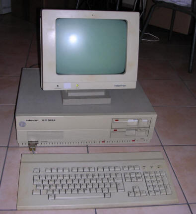
Robotron EC1834
Designed in Sommerda, but manufactured both in
Sommerda and Karl-Marx-Stadt plants, EC1834 was a true PC-clone computer
which surpassed even early originals with high-resolution graphics. As a
computer for professional applications: Databases, office systems or
multi-user services, it was possible to install 4 MFM hard disks, up to
40MB each. However not many users could afford this very expensive
option.
Another non-standard thing was its graphics adapter called just "COL" as
in Color. It was based on NEC uPD7220 chip, manufactured in GDR as
U82720 and had 256kB of VRAM and 4kB of SRAM (for text modes?). This
high-resolution color graphics chip, used in e.g. DEC Rainbow, allows to
go into 640x480 with 16 colors chosen from 4096-color palette. The only
problem: It was not compatible with VGA at all, only most CGA
compatibility has been achieved. As a cheaper version, a monochrome MON
card has been made too, for CAD applications it could be used
simultaneously with COL in two monitors (COL shown design, MON -
commands).
Although most of these computers had proprietary ISA 3-row pin
connectors, some export mainboards have 2 ISA slots for conventional
expansions. Usually German computer manufacturers avoided edge
connectors as they were prone to emitting and receiving electomagnetic
noise.
The computer was made both to internal market and for export, starting
ES PEVM (ЕС ПЭВМ)
series of "Unified System" PC-compatible machines. In 1988 a fully
AT-compatible successor has been designed, but probably never left
prototype stage.
| Manufacturer | VEB Robotron | |
| Origin | East Germany | |
| Year of unit | 1987? | |
| Year of introduction | 1986 | |
| Class | XT/AT/PS/2 | |
| CPU | Siemens 8086 | |
| Speed | 4.91MHz | |
| RAM | 640kB (256kB on board, 384kB expansion) | |
| ROM | Own simple BIOS | |
| Graphics | Text: 80x25 Graphics: Up to 640x480x16 colors, NEC uPD7220-based. |
|
| Sound | PC Speaker | |
| System expansion bus | ISA in non-standard connectors | |
| Floppy/removable media drives | 2x 5.25" 720kB
Quad-density drives, compatible with 320kB disks.
|
|
| Hard disk: | 40MB MFM (Robotron VS3 - ST251 clone/re-branded?) | |
|
Peripherals in collection: |
||
| Other cards:
|
FDD controller, HDD controller, Memory expansion, Serial port, Display card, All dedicated. | |
| Non-standard expansions: | "Robotron ISA" boards | |
| Operating system(s): | DOS, DCP 3.3 (DOS functional clone), MUTOS1834 (Unix-like), modified Windows 3.0. |
My unit is in fact a mix of two units. The primary one,
with casing, came with damaged bus drivers and a custom 12V DB9
connector on the rear. It came with no graphics card and adaptation of
ISA card using converter failed. Few months later I got a monitor,
keyboard (this time European, not German) and internals form another
unit. The mainboard has been replaced with video card. The computer is
now in working condition, yet boots from floppy - its original VS3 hard
disk has bad sectors in a very bad location and it's unable to boot from
it.
There is an unknown silver circular sticker in the front casing with
number "113014".
Among 34000 manufactured EC1834 units, there were different versions and revisions. My two mainboards have significant differences in interrupt circuits. One mainboard has only one 8259 (Siemens'), another one has two, giving additional IRQs in the middle row of "Robotron ISA" connector pins. There is also a DB9 connector with 5V and 12V for some external peripherals added after production, but, thinking from the condition of wires, still in factory.
In my opinion, German engineers got too close to western
technology going away form their own improvements tested in MMS16
systems. The casing is something I don't like to see in German hardware
known for precision (to verge on overengineering). It just falls apart!
Not that it's old and falls apart, it is just designed like the cheapest
Chinese casings, plus the terrible idea of the top cover opening to the
side like a book. Imagine opening this giant "book" in which the cover,
on its own weight, bends in all directions and tries to get off the
hinges. The only thing that looks like a solid, German electronics is
the power supply unit (OK, the display unit on Hungarian CRT looks also
quite well). There are many inventions and features which were used in
MMS16 (A7100, A7150) and not used in EC1834:
- Power supply unit is not digitally-controlled like in A7150, no
"wake-on-serial-port", no emergency stop on failure.
- BIOS is a drawback. In A7150 ACT does all the magic to make the computer
OK, then it starts the OS. Hard disk with unknown geometry? ACT will try
to detect some. Strange data coming from port? ACT tries to react (yet I
still don't know how). In EC1834 the BIOS is simple as in XTs - simple
POST, then boot the OS. In later ROM revisions there is a diagnostic
connector and 8255 emits some signals on it (like a POST test board) but
it is not well documented and dependent on BIOS version used.
- I have seen two A7150s stored in terrible conditions. Both have polymer
parts relatively good. I've seen 3 EC1834s. The one stored in basement
had no plastic parts as they fell apart. Other ones required complex
operations to keep old plastic parts in place. It looks that the quality
of plastic parts, especially in machines made in Karl-Marx-Stadt, was
worse.
And this for the price not much lower than A7150, a definitely more
complex PC with more parts inside and made using more expensive
technology?
| Contents: | Starting, jumpers | Pinouts | Links |
Starting, jumpers
The computer is, in software, a PC. It starts with memory counting, then it tries to boot from floppy, then hard disk. It can boot from 320kB floppy. The only things during disassembly which require to be cautious is weak plastics and removing the LED/speaker connectors, it's easy to rip wires from the plugs.
To configure hard disk used by controller, you need to
change DIP switches on controller card. Because the positions for "on"
and "off" in manuals of this PC is a mess, I'll just write "UP" and
"DOWN". "DOWN" means closer to the edge of the card where the slot is,
while "UP" is when the slider is closer to the chips. The order is from
the rear, towards the connector, like left->right if you hold the card
in front.
Probably you will see not 2, but 4 jumpers. The another two are for the
second drive and their geometry is the same as jumpers 1 and 2. If you
have one drive, just leave the second jumpers in any position (in my
unit they all were UP, UP).
| Geometry C/H/S | 1 | 2 | For example... |
| 820/6/17 (40MB) | UP | UP | Robotron VS2/VS3 or Seagate ST251 |
| 697/5/17 (30MB) | DOWN | UP | CDC WREN 94155-36 |
| 615/4/17 (20MB) | UP | DOWN | K5504.20 or Microscience HH725, ST225 |
| 1024/5/17 (40MB) | DOWN | DOWN | K5504.50 or Microscience HH1050 |
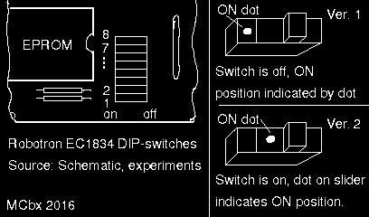
Now the mainboard jumpers. In GDR they used available parts, sometimes not ones from documentation. It means that there are at least two variations of DIP switches in which a dot indicates ON position (ON, current flows, contacts closed), in one of it, visible dot on slider means that it's on. A bigger chaos is introduced in EC1834's mainboard service manual giving "0" and "1" with DIP switches, which are BITS, not "opened" or "closed". It means that if switch conducts (is "ON"), then it drains pull-up current to ground, means... 0. For switch definitions I'm using convention shown in the picture below - ON towards EPROM, OFF towards resistor comb, switch 1 nearest board's edge:

Or if you are sure that nobody messed with mainboard,
use Switch 1 as the reference. It should be always OFF.
DIP switches functions:
| Switch | Function |
| 1 | Always OFF. It probably disables system boot at all (or from floppy?). |
| 2 | ON: No FPU, OFF - FPU installed |
| 3 | ON, ON - 256kB of RAM on board (as usual) |
| 4 | |
| 5 | ON, ON - reserved, OFF OFF - 80x25 text mode,
MON card ON OFF - 80-column, color card, OFF ON - 40-column, color card |
| 6 | |
| 7 | ON ON - 1 floppy disk drive, OFF ON - 2 floppy
disk drives ON OFF - 3 drives (untested), OFF OFF - 4 drives (untested) |
| 8 |
An explanation of this "chaos" in manual:
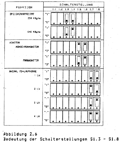
1. Picture from service manual showing "0" and
"1" contrary to DIP switches notation: |
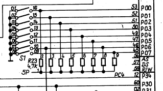
2. Part of schematic in which it can be seen
that "0" and "1" is not switch position, but bit state: |
COL card pinout:

1 - GND
2 - GND
3 - R
4 - G
5 - B
6 - GREEN (video signal for green monitor)
7 - ?some input?
8 - N.C.
9 - CSYNC.
My unit works with K7229.25 green monitor in at least a 80x25 mode..
http://developers-club.com/posts/216891/ - English description of
Soviet unit.
http://www.robotrontechnik.de/index.htm?/html/computer/ec1834.htm -
Description in German, Pinout of its 3-row ISA
http://www.robotron-computermuseum.efb-1.de/c_ec1834.htm - Photos of
computer and peripherals.
http://9hal.ath.cx/usr/digital-ag/archiv/ - Schematics. Don't trust
them, as modifications were included in production.
http://www.tiffe.de/Robotron/EC1834/ - More documentation and ROMs
http://www.ec1834.de/personalcomputer/index.php - Technical
documentation and not fragmented schematics.


