Chapter 2: Power supply unit
If you have a complete pinouts of power supply and video output, just verify
them with your hardware and find some compatible power supply unit (or build a
converter). If you don't have pinouts, you have to analyse power
connector and components. Start from the chips you know. Z80 CPU and 74xx logic
chips have +5V and GND pins. Triple-voltage RAM chips allow to trace -5V and
+12V. Some op-amps in tape circuits take -5V too, but don't be too sure of it.
Trace these voltage lines using PCB tracks and ohmmeter in "beeper" mode to
power connector (you will get pinout) or power regulator/converter block. then
analyse the block itself, see the voltages on capacitors and try to figure the
input voltages out.

The diagram above shows a typical power supply unit (abbreviated PSU)
for 8-bit computer (this one is suitable for
Commodore 64).
In most cases it is transformer-based one, not switching one. Power from mains
passes through (not shown) power switch, input filters and fuses (if present,
sometimes a DC switch is in computer). Then voltage
is decreased in transformer, the first block in our picture. AC coming from
transformer is rectified in diode bridge (usually Gretz or half-Gretz type) to
unregulated DC. After passing first capacitor (of a large capacity like 2200 or
4700uF, sometimes few capacitors connected in parallel), pulsing becomes smoother and its voltage increases to about 1.41*AC voltage. This voltage can be then
stabilized in 7805 regulator which ensures that no matter how much we draw (up
to 1A) we will get 5V from the power supply unit. The last capacitor stores
energy for sudden increases in consumption. It can be seen that 9V unregulated
AC is taken from the another winding of transformer and is used in computer.
Usually external power supply units contain transformer, maybe rectifier and
regulator. Some computers like
Dragon 32
or TI99 have
external transformer only (sometimes with very specific secondary coils), other
(like Sanco
TPC-8300) may work on unregulated DC, while
other (like
Atari 65XE or
Meritum)
have complete regulators inside external PSU.
Regulators may be linear (simpler, but not so efficient) or switching. Switching
power supply units don't have a big and heavy transformer. Some
computers like
Robotron KC85 or
Elwro 800
Junior have hybrid power supply units: transformers stepping down voltage to few tens of volts, then it
is converted to lower voltages in switching regulator. Some other computers use
switching power blocks working with 230V (e.g. some
Acorn BBC
models).

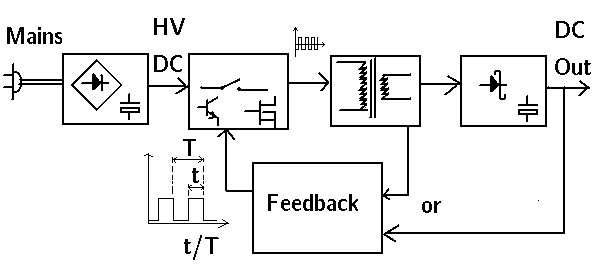
In the picture above we can see a very simplified diagram of a
switching-mode power supply unit. The main goal of a switching power supply unit is to reduce the
size and weight of a transformer. Also switching power supply units have better
efficiency, but they are more complicated. In most of them, mains power (in this
document sometimes referred to 230V, as 230V is in Europe), is directly
rectified to DC using a diode bridge and capacitors, giving about 400V DC. This
voltage is quickly turned on and off, usually in few kHz frequency, using
electronic switches based on conventional transistors or MOSFETs. Transformers
made for higher frequencies are smaller and more efficient, so the voltage is
decreased and current increases. Now it is only needed to rectify the resulting
few-kHz power coming from secondary side of transformer and we have few amps of
power in specified voltage using small power supply unit. To rectify such large frequencies a special
Schottky diodes are used, and to prevent impulses electrolytic capacitors are
installed in the output stage.
But how about voltage regulation when the receiver draws different current? It
is made by increasing or decreasing pulse width (t/T ration in the picture) coming to transformer. This
mechanism needs input, it comes from voltage comparator (comparing output
voltage with some low-current reference voltage) or by analysing magnetic field
in transformer's core. These units sometimes are driven by proprietary chips and
to turn the high voltage on and off they use large transistors. They are more
complicated in repair if something different than capacitors failed.
The most complex case is with very old and complex machines like Robotron A5120, in which
small, stand-by power supply unit allows to start high-power blocks giving 5 and
12V, and negative voltages are generated from them using smaller switching power
supply units. In technical documentation, the principle of operation of such
power supply unit takes few tens of pages.
If you service a switching power supply, remember that input capacitors may be
under high voltage even when power supply is turned off. About 400V DC in 230V
mains. This is dangerous voltage, so use insulated tools to discharge the
capacitors.
So if you don't have a power supply unit and there is no information about
proper voltage and current, evaluate which parts shown in the picture above are
built in computer.
If your computer has typical AC plug, verify that it is not shorted to
metal casing. You may also have a typical testing problem: If power supply is
broken (e.g. transformer primary winding short, shorted filtering capacitor) you
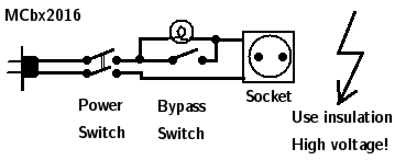
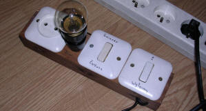
may blow fuses in your room. This problem may be diagnosed using apparatus shown
below.
 |
 |
It can be made using leftovers from house renovation and any
low-power incandescent light bulb (do not use compact discharge lamps or LED
bulbs). The usage is following: The power supply under test is connected to
socket, the apparatus is turned off and light bulb bypass is turned off. Now the main switch is turned on. Light bulb
may flash at this moment. A bright flash of a lightbulb at the beginning of a
test is normal, it's caused by input capacitors charging.
Now, if a light bulb constantly lights full bright, it means that there is a short in
tested power supppy unit. If it is glowing dimly, it means that everything seems
to be OK. You can turn the apparatus off, bypass light bulb with bypass switch
and turn it on again to power the computer up.
If it is totally off, power supply may not work at all (have you checked its
fuse?) or consume very small amount of power.
This device is really useful when dealing with unknown or uncertain electrical
devices.
If you have verified a computer, you have a complete CPU and you know how to
power it, try to connect power. Use a complete pinout of power supply, as
sometimes there are "Power good" signals which need to be supplied (e.g. shorted
to ground or 5V) to make the system start.
If the system has internal regulator and is using triple-voltage DRAM chips like
4116, quickly check presence of 5V and -5V. If -5V is absent, turn off the power
immidiately. Few seconds without negative voltage and DRAMs will be damaged.
If -5V is present, check are other voltages correct.
|
|
|
MCbx 2016