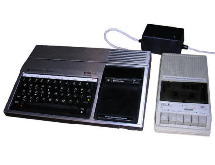
Texas Instruments TI-99/4A
In 1981 Texas Instruments released TI99/4, the first
series of 16-bit home computers. The computer has a Texas Instruments
TMS9900 processor running at 3MHz. It has a true 16-bit bus and works at
3MHz, so it was needed to use very fast memory chips: Static RAM. But
static RAM was expensive, so engineers designed only 256 bytes of SRAM for quick
access. 16kB of 8-bit normal dynamic RAM used (by design) for graphics purposes is placed on
a 8-bit bus and is significantly slower.
The similar thing is with ROM: TI99 has 8kB of its own ROM and serially
available "GROM" - Graphics ROM. This memory is initialized at some
address and read byte by byte, every byte a "pointer" advances one byte
forward.
TI99 gained its popularity in USA as a home computer and game console,
as many games have been released on ROM cartridges (called Modules). It was possible to
expand it using a modular rack for many cartridges, floppy disk drive or
memory expansion. In Europe it was quite rare because of strict export
laws and lack of applications of so memory-constrained systems.
| Manufacturer | Texas Instruments | |
| Origin | USA | |
| Year of unit | 1982 | |
| Year of introduction | 1981 | |
| End of production | 1983 | |
| CPU | TMS9900 | |
| Speed | 3MHz | |
| RAM | 256B "Scratchpad RAM" 16kB graphics RAM |
|
| ROM | 8kB 18kB Serial ROM (GROM) |
|
| Colors: | 16 | |
| Sound: | 3 channels | |
| OS: | Basic, many expansions | |
| Display modes: | Text: 32x26, 40x24
(mono) Graphics: 48x64, 256x192. |
|
| Media: | Tape, cartridge | |
|
Power supply: |
||
|
|
||
| I/O: | Keyboard Joystick port for 2 joysticks (multiplexed) Video output System bus Cartridge slot Tape I/O for 2 recorders (Switched) |
|
| Possible upgrades: | With | |
| Other peripherals in collection: -- Texas Instruments Program Recorder cassette deck. -- Game cartridge "Schachmeister". |
||
| Software accessibility: | TOSEC, dedicated sites |
My unit is in relatively good condition. It is one of these European PAL units with YPbPr output, not composite.
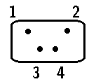
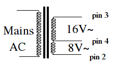
Important note about internal power supply pinout.
The internal power supply connector's pinout, if used to power the
computer externally (or power regulator PCB replaced) should be compared
using ohmmeter with a real hardware, +5V and ground can be checked with
power pins of any TTL chip, -5V and +12V with DRAM 4116 chips.
Just don't trust any schematic, but test conductivity of IC connections
with proper pins in power plug (disconnect plug from regulator before)
in YOUR MAINBOARD. The pinout shown in schematic from technical manual
(-5V, +12V, GND, +5V starting from sharp part) is totally different
than in my unit (+12V, +5V, GND, -5V starting from sharp part). In
another schematic accessible
here,
I can read another pinout: +5V, +12V, GND, -5V. It means that
in different versions and revisions, the pinout of power connections
changes. Do not damage your TI99 by giving it improper voltages from
replaced regulator module or PC power supply. And if you power it up
using PC power supply, do not disconnect -5V with other voltages
present. This gives a really bad results on DRAM.
According to
this
source, my TI99/4A has TI99/4 power regulator module and has totally
non-standard pinout.
During disassembly, be careful with power switch lever, is is fragile. There is also a cartridge port riser which should be inserted during reassembly.
| Contents: | Starting | Tapes | Pinouts | Power plug | Links |
Starting:
Computer starts to boot screen, then (if no cartridge is installed) when key is pressed, it allows to choose operating environment to run. Bare computer has only normal TI BASIC, so it can load and save programs only in TI BASIC, not in e.g. Extended BASIC (which can be started from cartridge). In TI BASIC, you can load program by positioning your tape and typing (ALPHA LOCK key down!):
OLD CS1
There is no program name on tape, so you have to rely on
your tape recorder's counter.
You may meet 2 errors: NO DATA FOUND means that there's no difference on
line for some time - volume is too low or too high. If you get ERROR IN
DATA, you can make computer read a fragment again. Press R, then rewind
as prompted. If it have read more (tape advanced after replaying), you
just increase volume a bit. If it can't read before first error,
decrease volume. It is convenient to remember the counter position
during this process.
To save program, go with:
SAVE CS1
Computer will ask to verify program, which is quite useful. Remember that if you get message like "PRESS ... THEN PRESS ENTER" it usually doesn't wait for this Enter :).
And again, you don't have any method of tape navigation other than a counter. And in fact TI BASIC is a really poor BASIC implementation with only the most simple commands. It cannot access most of available program memory easily, so Extended BASIC programs are usually just too large for it.
Preparing tapes
TI99 is very simple about file types, so it is urually easy to convert program recorded on tape to disk. It is harder in reverse. The typical way to transfer disk images is to use DSK, and programs is Fles In A Disk: FIAD. There are also compressed FIAD which can be uncompressed on TI99 with Extended BASIC and Archiver software.
To extract file from DSK image to TIFILES, use TIImageTool. You will get TIFILE type files, which are a type of FIAD. TIFILES have special marks inside to be transferred serially to TI99. This Java program works nice even in Linux.
To convert FIAD to sounds, you can use CS1er or Tape994a programs. CS1er works well with Linux and Wine, Tape994a will run only on Windows.
In fact, there is also one more format called V9T9 FIAD, and CS1er should have support for it. See here for details.
About cartridges... This is quite difficult. You will have problems if you think about burning EPROM, putting in some magic PCB and having a new cartridge. The cartridge memory is divided to ROM, maximum 8kB (but sometimes can be bank-switched like in some C64 cartridges) and serially-accessible GROM - Graphics ROM. After reading a byte from initialized GROM, the virtual "pointer" moves to next one and you can read it. This solution is perfect when keeping pictures, but is not good for random access. As with Commodore 64 there are different ways to build a cartridge.
Pinouts
Video pinout For European 'component video' YPbPr version only:
|
|
| 1 - +12V DC 2 - Y (you can use it as composite monochrome) 3 - Pr (R-Y) 4 - Pb (B-Y) 5 - Audio 6 - GND |
There are at least 3 versions of video connector. DIN5 with composite, DIN5 with component (very rare) or DIN6 with component like this one. You have been warned.
Cassette port pinout:
|
|
| 1,2 - Deck 1, start/stop (1 to tip) 3,5 - Output to deck(3 to GND) 4 - Audio gate (??) 6,7 - Deck 2, start/stop (6 to tip) 8,9 - Input from deck (9 to GND) |
You should be aware that all connectors have their own ground connections. The original cable had 5 connectors, In, Out and Start/stop to Deck 1, and Out and Start/Stop to Recorder 2. Recorder 2 cannot load programs, it can only save taking signal from computer's output. It was made intentionally not to destroy decks' outputs when two of them are playing simultaneously. Usually only single deck 1 is used.
Joystick port pinout
|
|
| 1 - NC 2 - Select joystick 2 3 - Up 4 - Fire 5 - Left 6 - NC 7 - Select joystick 1 8 - Down 9 - Right |
In TI99, two joysticks share the same connections for Up/Down/Right/Left/Fire. They are multiplexed (switched very fast) as two additional keyboard rows. Joystick becomes "selected" when there is -0,5V in the proper Select line. All other time there is 5V on it. Commodore joysticks can be used with adapter.
Making power plug
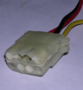
| To make power plug for your TI99, you have to use 2 female Molex (in fact the proper name is AMP plug, but Molex is the popular name of these) plugs from old PC AT/ATX power supply unit, like these ones for connecting PATA hard drives or CD/DVD drives. You can see such plug in the picture. First, remove wires with metal parts from plastic plugs by pressing the metal protrusions in plugs' holes. Remove all wires. Select 3 of them you will use. I recommend using 3 different colors (Red, yellow and black in typical AT/X Molex plug), it makes further connections easier. Now prepare one plug by sticking two wires in the middle holes of it, and second plug by sticking single wire in the LEFTMOST hole (looking towards rear of plug, means front of TI99's connector and having trapezoidal side pointing upwards). Before, you may need to bend the small metal protrusions on metal parts of wires again to make them hook inside plastic plug, because you've bent them in the opposite direction when removing wires. Don't deform them too much there. |
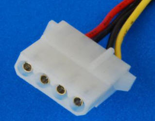 |
Now using small screwdriver make the metal rings a bit
bigger by bending them outwards a bit. Pins in TI99's connector are
bigger, so they need to be a bit bigger. Sticking one connector a time
make them fit to upper (single pin on the left of the TI99) and lower
(pins closer to each other) part of TI99's socket. Verify with pinout
that single pin in plug does not go to NC pin (are you sure you haven't
made a mistake? Maybe I made?), and both plugs are going with right
angles surfaces facing together, chamfered outwards.
Now if you put the plugs with right angle (flat, without trapezoidal
cut-offs) faces together, you will get a single plug with roughly shape
of TI99's power socket, but with too big spacing between upper and lower
pins. This is normal.
Links
http://shawweb.myzen.co.uk/stephen/TI.htm - "Getting Started with
TI-99/4A" book online and MESS emulation instructions.
http://www.chiark.greenend.org.uk/~pmaydell/hardware/tapeth/ -
Description of one of computer
http://web.archive.org/web/20140923060256/http://www.ninerpedia.org/index.php/Media
- What media can be supported?
http://web.archive.org/web/20141012233723/http://www.ninerpedia.org/index.php/Formats
- File formats of floppy images and ROM dumps.
http://www.mainbyte.com/ti99/hardware/cassette/recorder.html -
Cassette recorder manual
http://www.mainbyte.com/ti99/index.html - Interesting site about
TI99
http://www.mainbyte.com/ti99/man/console.html - Service manual with
schematic of USA version
http://www.unige.ch/medecine/nouspikel/ti99/titechpages.htm - Technical resources
http://atariage.com/forums/topic/217298-good-joystick-for-my-old-ti994a/?p=2841169
- Connect two joysticks to TI99 (they're multiplexed).
http://www.robotsandcomputers.com/computers/ti_994A.htm - Pinouts
and downloadable manuals
http://www.dsapsc.com/home-brew-hardware.html - Sound mod
http://www.harmlesslion.com/text/TI%2032k%20Mod.pdf - Memory mod
http://tigameshelf.net/ - Game
archive
https://ftp.whtech.com/ - One of the biggest servers with TI99 resources.
http://www.harmlesslion.com/cgi-bin/showprog.cgi?search=Classic99 -
Probably the most known emulator.
http://www.mrousseau.org/programs/ti99sim/ - Emulator, one of many.


