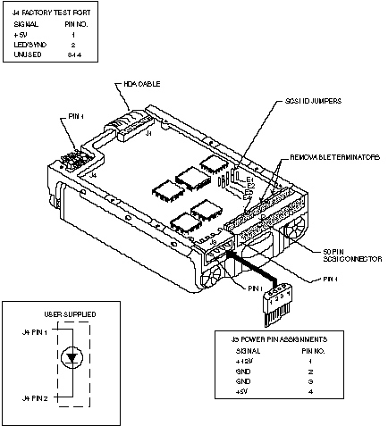
There are four jumpers available for configuration. Three of the jumpers, E2, E3 and E4 are used to select the drive's SCSI ID, while E1 (installed) disables parity. The following table defines the settings for these jumpers.
| E2 | E3 | E4 | Device |
|---|---|---|---|
| OUT | OUT | OUT | 0 |
| IN | OUT | OUT | 1 |
| OUT | IN | OUT | 2 |
| IN | IN | OUT | 3 |
| OUT | OUT | IN | 4 |
| IN | OUT | IN | 5 |
| OUT | IN | IN | 6 |
| IN | IN | IN | 7 |

| Mounting Holes |
|---|
| Side: 6-32 UNC-2B .12 Max. Insertion Bottom: 6-32 UNC-2B >.25 Max. Insertion |